Taming the Wild BOM: Why You Need a PLM System to Corral Your Data
Learn why you need a PLM system to help corral your data in our latest blog.


I am often asked about waste pipe sizing in Revit MEP, and the simple answer is that Revit does not size sanitary systems. That doesn’t mean however that the information available in a sanitary system can’t be used to help with the process of sizing.
Sanitary Systems in Revit MEP
If you are using Revit MEP for sanitary systems, you will probably have come across something called a Fixture Unit. Fixture Units are applied to individual Revit Plumbing Fixtures and will give a cumulative total of all the fixture units in a sanitary system, which in turn equates to a flow rate through that system.
Below we see the Waste Fixture Unit value found in the Type Properties of a Plumbing Fixture. You will also see values for Hot and Cold Water Fixture Units.

Waste Fixture Unit Value found in the Type Properties of a Plumbing Fixture
In the Mechanical Settings of Revit MEP, we see an explanation of what Fixture Units are and how they are used in determining flow rates and pipe sizing. However, the pipe sizing aspect only applies to domestic hot and cold water systems, and does not extend to sanitary systems.
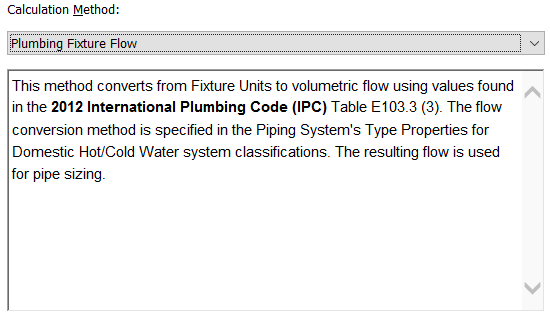
Mechanical Settings of Revit MEP
We can however still make use of the total number of fixture units found in a sanitary system and make our own calculation to determine pipe size.
Using the Fixture Unit Information in our Sanitary System
Just to make things a bit easier let’s start by calling a Fixture Unit a Demand Unit instead. Below we can see the number of elements in our system, each with 1.7 DUs (as shown above) giving us a total of 81.6 DUs in the stack.
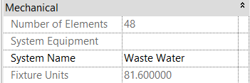
By using the total number of DUs in the system and applying an appropriate frequency factor we can calculate the flow rate in the system and therefore establish a minimum stack size. Any time something changes in our system we re-calculate to ensure our stack size remains adequate.
Using Dynamo to Harvest the Design Data
The section of script below is used to extract the total number of DUs in each system, the System Name, and a value for the Frequency Factor (this was added to the project as a shared parameter and is altered as necessary from within the project).
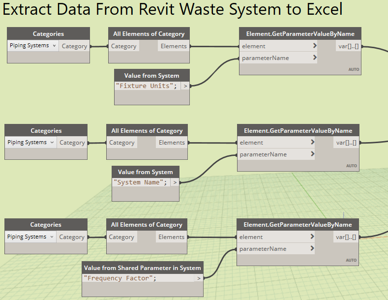
This information is then sorted within Dynamo and exported to Excel as shown below:
![]()
The Calculated Flow Rate is derived using the following calculation within Excel:

Then the Minimum Stack Size is determined by the following IF statement within Excel:

If the calculated flow rate determines that a pipe size of 150mm is insufficient, then a “Check System” message is returned.
The calculated flow rate and minimum stack size values are then pushed back into Revit where previously created shared parameters are automatically populated, shown in the following section of Dynamo script:
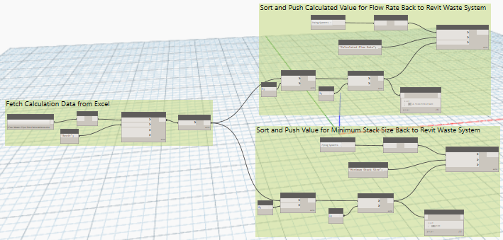
The results can be seen in the Piping System Properties as shown below:
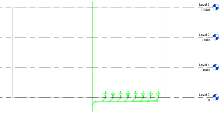
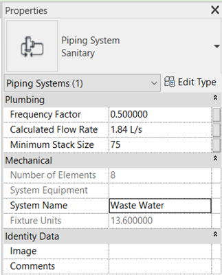

As the Demand Units on the waste system increase, so the calculated flow rate increases. The updated information is automatically extracted by Dynamo to Excel where the calculation is updated, and the results pushed back to Revit.
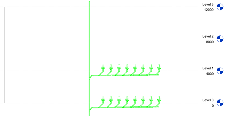
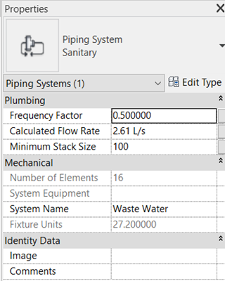
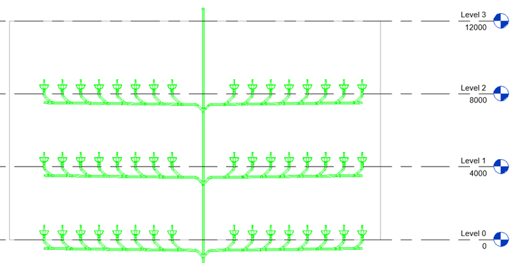
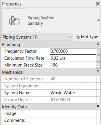
An increase in the number of plumbing fixtures and an increase in the Frequency Factor value results in a greater flow rate than can be accommodated in 100mm diameter pipe, so the minimum stack size is increased to 150mm, indicating that the stack size needs to be increased.
This workflow could be extended to drive the changing size of the pipework within the project, or you could simply create a schedule to compare the calculated size of the stack against the actual size.
The calculations performed in Excel could be carried out in Autodesk Dynamo itself, however, it may be preferable for team members who do not use Revit to be able to see this data in a more familiar environment.
If you are interested in learning more about Revit MEP or understanding how Dynamo can help you achieve your aims in Digital Engineering, then contact us directly and we would be happy to discuss your specific needs.
Learn why you need a PLM system to help corral your data in our latest blog.
Learn about BIM to GIS Collaboration Patterns Between Owners, AEC Firms, and Municipalities in our most recent blog post.
Learn about the Dynamic Duo of Water Infrastructure Management through Autodesk’s InfoWater Pro and Esri ArcGIS in our most recent blog post.
