Taming the Wild BOM: Why You Need a PLM System to Corral Your Data
Learn why you need a PLM system to help corral your data in our latest blog.

When working with structural elements it is very common to either place tags showing type marks or the actual dimensions of the element.

For example, a ground beam may be tagged with a type mark as shown in the left hand image or the full callup shown on the right.
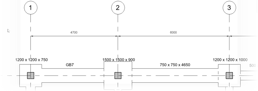
If you are using a type mark then this is usually a case of creating a schedule and manually typing each type mark. If you are using the full callup then you have to rely on the family type name which may not reflect the actual dimensions of the element!
Fortunately, there is a more efficient and accurate method using the Naviate Accelerate tools from Symetri. These tools, used in a workflow provide a great way of creating type marks or full callups that reflect the actual dimensions of each structural element. The process starts by using the Edit tool within the Parameter Values ribbon panel.

The Edit parameter tool will allow us to see all of our type and instance parameters in a grid view where we can organize the data by column and then copy fill or increment the actual values. Once the Edit tool is clicked you will be prompted to select either type or instance parameters. In our example, the Type Mark is located within the Type parameters
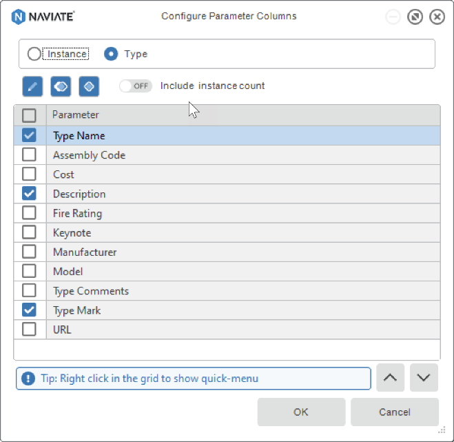
By organizing the families by type name and description, the ground beams can easily be identified. You can then enter the first designation such as GB1 and then use the green plus icon to increment this down the rows.
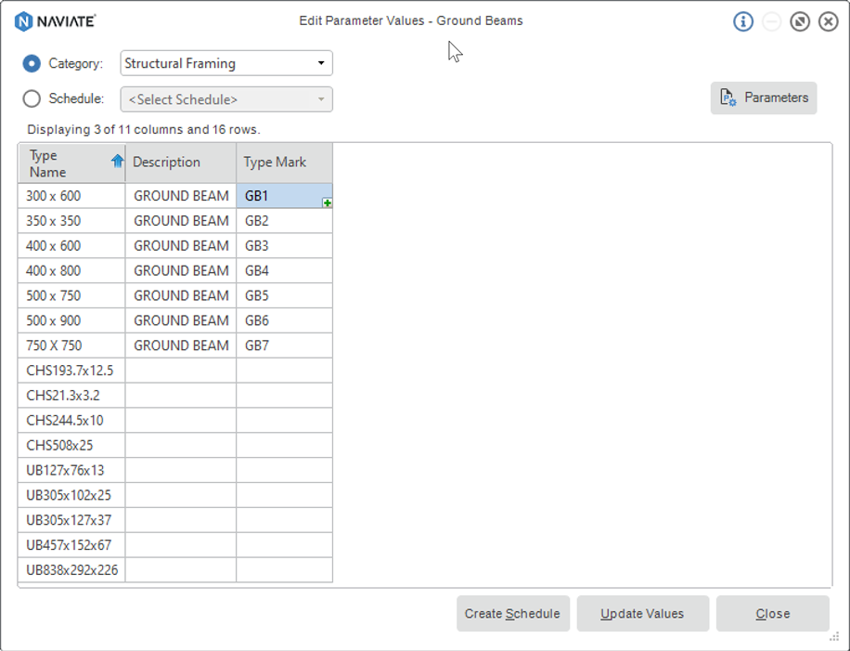
You will then have the option of creating a schedule from this which we can use as a ground beam key on drawings. When you click the Update Values button the type parameters are created for each beam type. In the example below, the b and h type parameters are combined with the cut length of the beam to describe the exact dimensions.
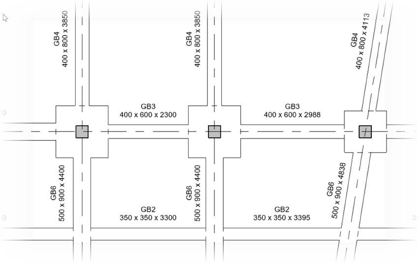
To ensure that you always have the correct dimensions on your tags you can use another Naviate tool named ‘Combine Parameters.’

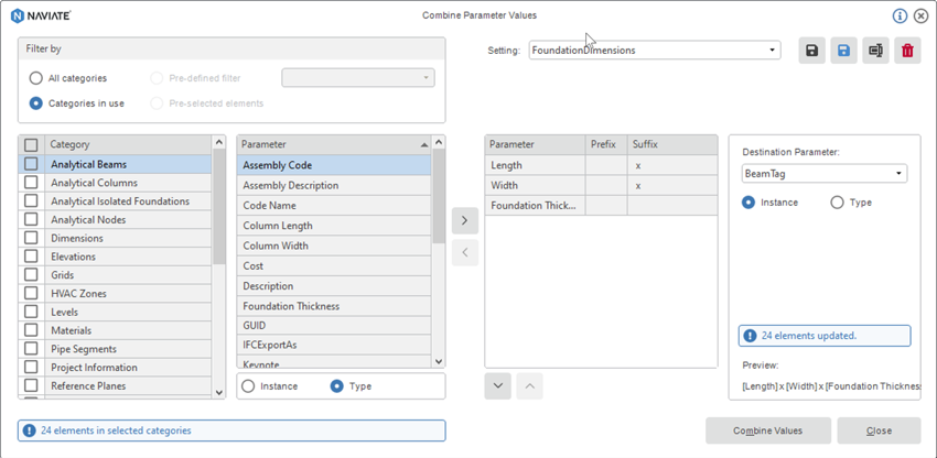
The combine parameter tool allows you to access type or instance parameters across multiple categories and write these to another parameter. This can be used for all sorts of tasks but tagging elements by their physical size in an obvious use case.
In the Combine Parameter Values dialog, you can select your categories and then add parameters to combine. In this example, the Length, Width and Foundation Thickness are added along with the suffix ‘x’ to generate the naming convention. This is then written to the BeamTag instance parameter (This is a shared Parameter that I created). Finally, you save the settings so that the parameters can be updated if the elements change size.
In our world of ‘BIM’ the key drivers are collaboration, efficiency, and accuracy. These simple tools used in the above workflow enable faster, more accurate information that is used within your construction drawings, schedules and also written into your shared parameters, or the Revit built in parameters. Of course, this data is then viewable in IFC’s and other tools such as BIM360.
For more information on Naviate and the tools available that you can benefit from please click here.
Learn why you need a PLM system to help corral your data in our latest blog.
Learn about BIM to GIS Collaboration Patterns Between Owners, AEC Firms, and Municipalities in our most recent blog post.
Learn about the Dynamic Duo of Water Infrastructure Management through Autodesk’s InfoWater Pro and Esri ArcGIS in our most recent blog post.
