When you are modeling grading objects in Civil 3D, you may require using different slopes along the same feature line. While this is simple enough (just select ‘No’ when you get the ‘Apply to entire length?’ prompt in the command line), modeling the transition between those grading objects can require more care.

If the transition occurs along a straight line, you can use the ‘Create Transition’ tool, as shown below:
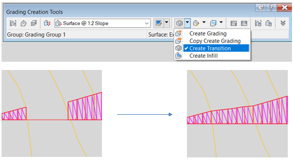
However, this tool in Civil 3D will not help if you want the transition to take place on a corner. In that particular case, the process is more manual. You will need to complete the top or toe of the slope with a feature line and then model the transition as an infill. The workflow is detailed below:
- Draw a feature line for the top of the cut or the toe of the fill slope in the transition. Make sure that you get the elevations of the feature line from the target surface.
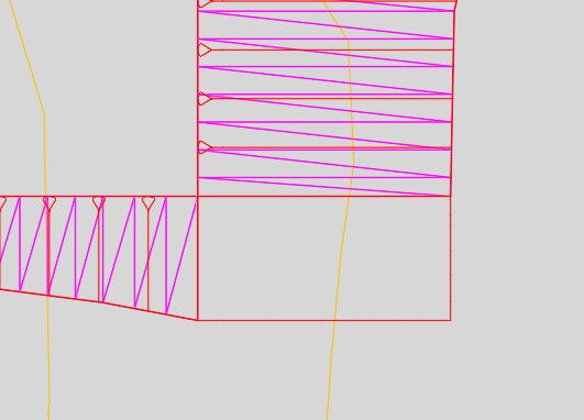
- Select the feature line and use the ‘Insert Elevation Point’ tool from the contextual ribbon to add some intermediate points that will then be used for the surface triangulation. Select the option ‘Increment’ from the command line and type the desired distance between points (e.g. 1 m).
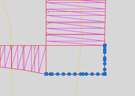
- Create a grading infill for the transition.
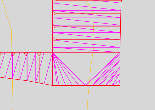
- If the triangles are not oriented in the desired direction, select the surface that is attached to the grading object and use the ‘Edit Surface -> Swap Edge’ tool from the contextual ribbon.
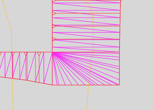
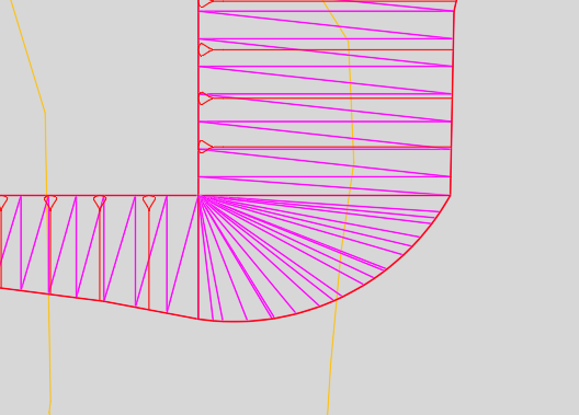
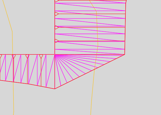
Depending on the constraints that you have, you may want to model the transition with a different geometry like an arc or a straight line.
I hope you found this useful. If you’re looking for further assistance with Autodesk Civil 3D to improve drafting, design, and construction documentation, we provide consultancy and training based on your specific needs.
We offer private and scheduled AutoCAD Civil 3D training courses, find out more here.


